
The Art of Mandrel Tube Bending
The full Turn-Key package. If you are purchasing or have purchased a tube bending machine the following information will guide you on your way to manufacturing quality components. The main ingredients to manufacturing a superior quality component are. Tooling, Setting and a little splash of Lubricant.
Tooling
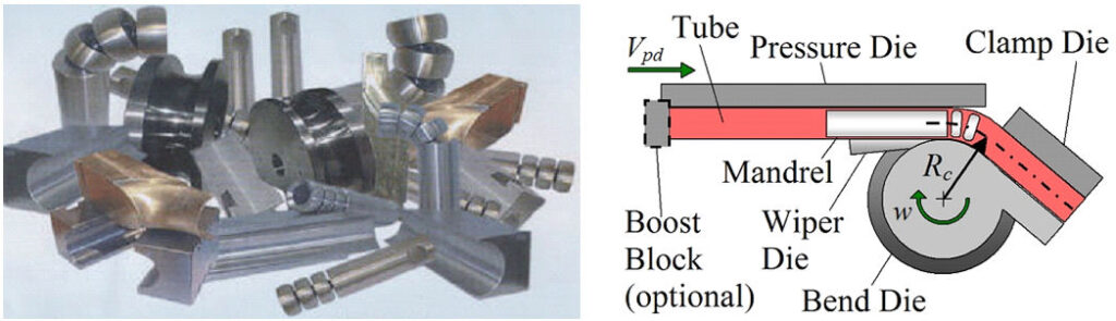
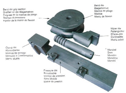
Bend-formers Sometimes referred to as a Bend Die. This is the main tool around which the tube bends. It has the shape of the tube machined around the periphery to contain it during the bending process. The radius from the centre of the former to the centre of the tube is referred to as the CLR (centre line radius). Bend radius may also be referred to by the relationship of the tube diameter to the CLR. For example, 60mm Diameter tube bent on a 180mm CLR would be referred to as a 3D bend (3 x tube diameter = 180). Similarly, the same 60mm tube on a 60mm CLR would be a 1D bend.
The straight section of the bend-former is called the former extension. This may be machined as one piece or be detachable, if detachable it can be replaced with a different type of gripping surface. The bend radius and the resistance of the tube to bending determine the type of extension selection. As a generalisation the tighter a bend radius is, the longer the clamp area needs to be to overcome the additional resistance, although serrations or coating the gripping face will assist to keeping the length to a minimum.
Loose Clamp Sometimes referred to as the Clamp Die. This is the moving block used to grip the tube with the bend-former during bending. It has a machined form corresponding to the bend former. The amount of gap between the former and clamp when in the closed position will depend on the thickness of the tube. It is permissible to have a slight pinch on this item to improve grip. The clamp should never be permitted to crush the tube onto the mandrel especially the ball type. This practice will certainly result in damage to the balls and mandrel linkage.
Pressure Slide Sometimes referred to as the Pressure Die. This piece of the tooling is designed to force the tube into the profile of the former. The pressure slide is allowed free linear movement to travel with the tube during bending. Pressure dies may be static depending on the materials and bend CLR. To bend thin wall tubes, typically to aerospace specifications and as a designed feature, a power follower slide may be fitted to the machine to provide hydraulic assistance to the linear travel of the pressure die. This should be adjustable in pressure and feed
rate and will help to overcome drag, which, on materials such as aluminium will result in excessive wall thinning. Clamp slippage may also be a result of drag.
Mandrels The mandrel is the tool positioned inside the tube and firmly anchored to the back of the machine with a stretch resistant rod during bending. The shank or body of the mandrel is the portion over which the tube is drawn and initially determines the quality and shape of the outside of the bend. On bends in tube likely to collapse due to a high relationship between the tube O/D to wall thickness it will be necessary to extend the support beyond the tangent point by use of ball segments mounted to the shank. The number of balls required is relative to the bend radius, the O/D to wall thickness ratio and the bend angle. The function of the balls is to internally support the shape of the tube and prevent flatting occurring after leaving the tangent point. If flattening is permitted to occur or if the support is inadequate, wrinkles will result on the inside of the bend.
There should be a mandrel retraction unit fitted to your machine, this will retract the mandrel balls from inside the tube at or just before the end of the bending cycle usually 2-5 degrees depending on the type of mandrel in use and lubricant. This is sometimes referred to as anticipated or controlled mandrel retraction. Knowing this we have manufactured a lubricant that has been proven to reduce friction and lengthen tool life. To find out more about this lubricant for your application contact us.
The Wiper Die The function of a wiper die is to prevent wrinkles forming on the inside of the bend. You will find This is common when bending a 1D bend. The material wiper dies are made from will depend on the material to be bent. This item also plays a vital role in the production of bending thin wall tube.
The profile of the tube should be precisely manufactured to a true form within the wiper. The size and quality of the profile should permit the material to flow without any resistance. An oversize profile will allow the material to grow vertically, and this may cause wrinkles, whilst a tight profile will cause drag, followed by clamp slippage. this should be avoided. A badly fitted wiper die will result in failure to achieve a wrinkle free bend and damage the wiper tip.
Setting Your Tube Bending Machine
Your Machine To fit the tools onto the machine, first ensure that the mounting faces are clean and free from debris. Back off the loose clamp and pressure die holders so that even at full stroke they would not reach the bend former. This is for your own safety and protection of the tooling.
The Bend-former the bend-former should be a good fit on the centre spindle or its location rings/key and should not be permitted to lift during bending. A good fit and alignment with the key (if fitted) will ensure that the former extension on the bend-former will also be parallel to the loose clamp to give maximum gripping performance. If a tie bar is fitted to your machine, we recommend you use it. This will improve the chances of a good bend because of its stabilising effect on the centre spindle and the avoidance of undue stresses on the machine head assembly.
The Loose clamp This part should be of adequate length to provide gripping ability without excessive force being applied. Care should be taken to ensure that the vertical alignment of the profile is correct. Placing a solid bar or sized tube in position at an early setting up stage before pressure loading is applied and before the clamp is locked into its vertical position.
The Pressure Slide or Roller The pressure slide should be of adequate length to travel to the required angle of bend and still maintain a minimum 2 x D of support. The vertical alignment of this part is vital and can be achieved in the same way as the loose clamp. Ensure that the alignment of the pressure slide profile is parallel to the profile in the bend former.
The Mandrel and Lubrication Setting the mandrel in the correct position is regarded by many as an art form. For example, a badly fitting or loose mandrel will need to be set ahead of the true centre line to compensate for the excessive clearance between its diameter and the tube I/D. On the other hand, a tight mandrel may have to be slightly behind centre to avoid tube breakage on some materials. As a rule, the end of the mandrel shank should be on or slightly back of centreline by no more than 1mm initially. If a ball mandrel is being used, the stroke of the mandrel retraction cylinder should be enough to withdraw all the balls from a completed bend. At this point lubrication plays a large part in the setting of your machine. To reduce the angle of mandrel retraction can depend on the mandrel lubricant you use, this can make all the difference between a flat bend and a full bend. if the wrong lubricant is used the usual result is broken links or cables. Knowing this we have manufactured a tube lubricant that has been proven to reduce friction and lengthen tool life. To find out more about this lubricant for your application contact us.
The Wiper Die To align the wiper-die correctly, the bracket should have adjustment in all axes, i.e., forward, and backward, up, and down of the centreline and of the rake angle. The bracket face on which the wiper die is to be mounted should be 90deg to the vertical axis of the bend-former profile.
To fit a wiper-die, position the die and bracket in an approximate position and secure them finger tight with core. Advance the wiper die towards centre line of the bend-former, keeping it parallel to the pressure die in both axes using either the jacking screws on your bracket or gentle tapping with a soft mallet in a non – vulnerable area. The bottom of the groove should not rise above the level of the bottom of the clamp groove on the bend die. Using a straight edge or rule, can check this. When the head of the wiper die is neatly fitted into the bend-former groove and the grooves are level, this is the optimum position. You will note that the wiper die is not at the true centre for reasons mentioned in the wiper die section. A slight “negative rake” angle on the wiper die will assist in assuring that the back – end does not combine with the force of the pressure die to create a clamping effect. When all these factors are correct, fully tighten the bracket and wiper die in position, checking that the tightening action does not alter positions.
Great value New and Refurbished CNC and Semi-Automatic mandrel tube bending machines to suit all budgets. Complete with: Full parts and labour peace of mind warranty, Installation, commissioning, and full operator training including tooling selection and tooling setting. Mouse here to download your copy of the buyers guide
[…] See and read more […]